Deuteron Technologies makes a series of Attenuator Test Accessories to help users check and understand the operation of neural loggers and other neural data acquisition equipment. They come in varieties of 16, 32, 64 or 128 channels.
An Attenuator Test Accessory takes a single audio-frequency signal from an external source, and feeds it to an array of switches. The signal coming from each switch is then reduced in amplitude (attenuated) by a large factor and then fed into a connector. A neural logger that is mounted on this connector can thus be tested, and demonstrated to be operating correctly.
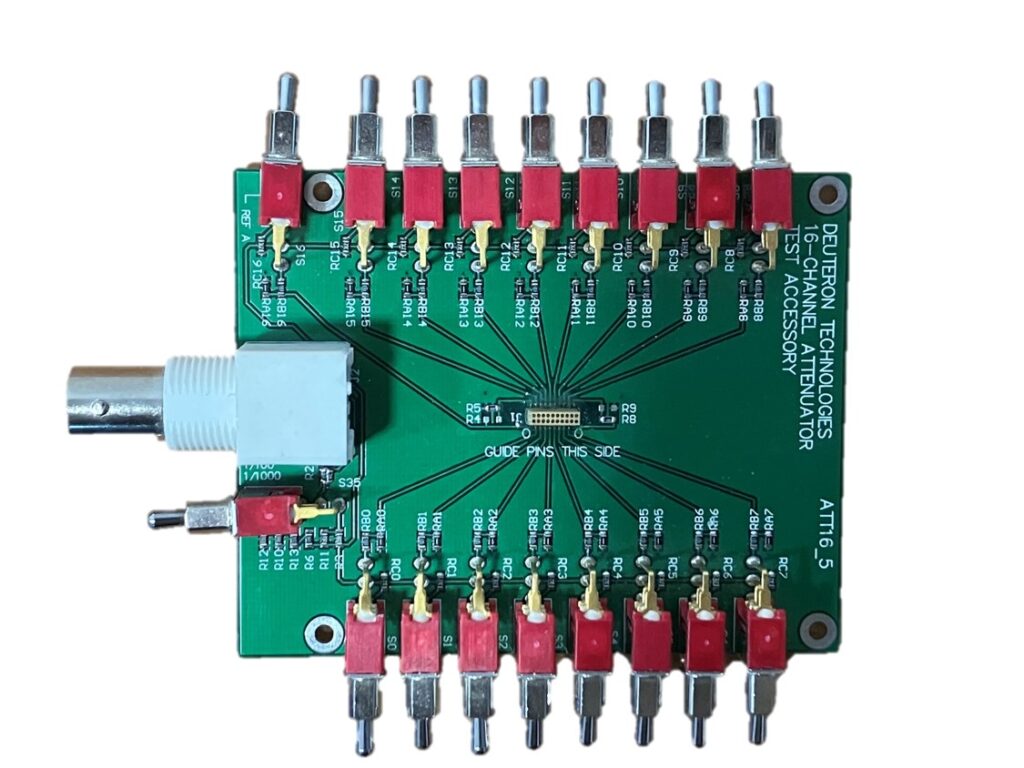
All Deuteron Attenuator Test Accessories provide a switch that allows the selected attenuation factor to be either 100 or 1000. The attenuation factor of 1000 is usually used. This allows the external signal to provide a signal with of amplitude between zero and 5V to make simulated neural signals with amplitude in the range zero to 5mV, which roughly matches the input range of a neural logger. The attenuation is needed because typical signal sources cannot accurately control signal levels in the microvolt to millivolt range.
A wide variety of signal sources can be used to drive the attenuator Test Accessory. Examples include commonplace laboratory signal generators, the audio output of a computer, or the analog output of a data acquisition system.
Attenuator Test Accessories can be used for a variety of test operations, for example:
- Testing the signal bandwidth of a logger or other equipment
- Checking the channel mapping of a logger or other equipment
- Checking linearity or digitization qualities of a logger or other equipment
- Checking that all channels are working in a logger or other equipment
- Checking the amplitude calibration of a logger or other equipment
- Checking for open or short circuits of wiring or within neural recording equipment.
- Checking the operation of reference channels of a neural logger.
- Checking adapters and extension cables
The Attenuator Test accessory is not intended for testing the noise level (sensitivity) of a logger. For this, we recommend using a resistively terminated connector that matches the logger’s connector. This is because the Attenuator Test Accessory is physically quite large and not fully shielded, so that it can pick up some environmental electrical noise.
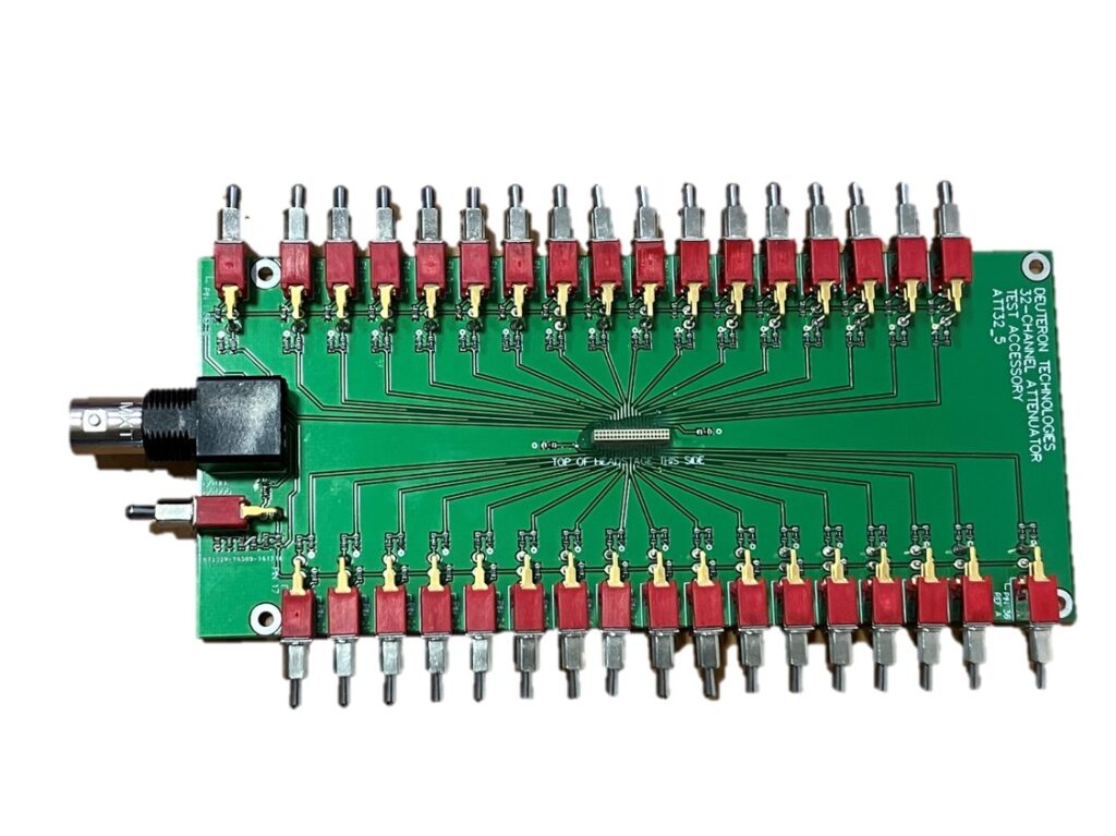
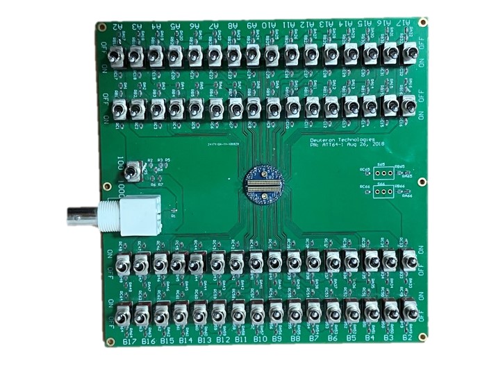
The array of switches of an Attenuator Test Accessory is always arranged physically in the pattern of a scaled-up picture of the connector for a logger. This ensures that it is easy to know which switch controls which pin of the connector.
For almost all tests, a known signal is applied to the BNC input of the Attenuator Test Accessory, and its properties are compared with the signal recorded by the logger or other equipment. When using a Deuteron neural logger, this is most quickly done using the “Neural monitor” feature. Alternatively, the data can be recorded as usual onto a memory card, and then analysed using any familiar data analysis software.
Checking Channel mapping
Channel mapping is the relationship between the index of a channel as seen in an array of recorded data and the physical pin number of a neural signal connector. Channel mapping is often inconsistent between different pieces of neural recording equipment. Furthermore, the channel mapping of some systems can be changed by the ser, so it also depends on the configuration of the equipment. The channel mapping of Deuteron neural loggers can be changed using the LoggerCommand program, but doing so is generally not recommended, because of the confusion that this can cause.
It is best to keep using the default channel mapping with which Deuteron Loggers are usually shipped.
An easy way to check channel mapping is to view a stream of neural data, for example using the Neural Monitor feature. One can switch on and off a particular channel on the Attenuator Text Accessory and see which channel responds in the stream of data in the monitor or the recorded data.
16, 32, and 64-Channel Versions
These Attenuator Test Accessories use only passive components and therefore require no power supply, and can be used with almost any signal range
128-Channel Version
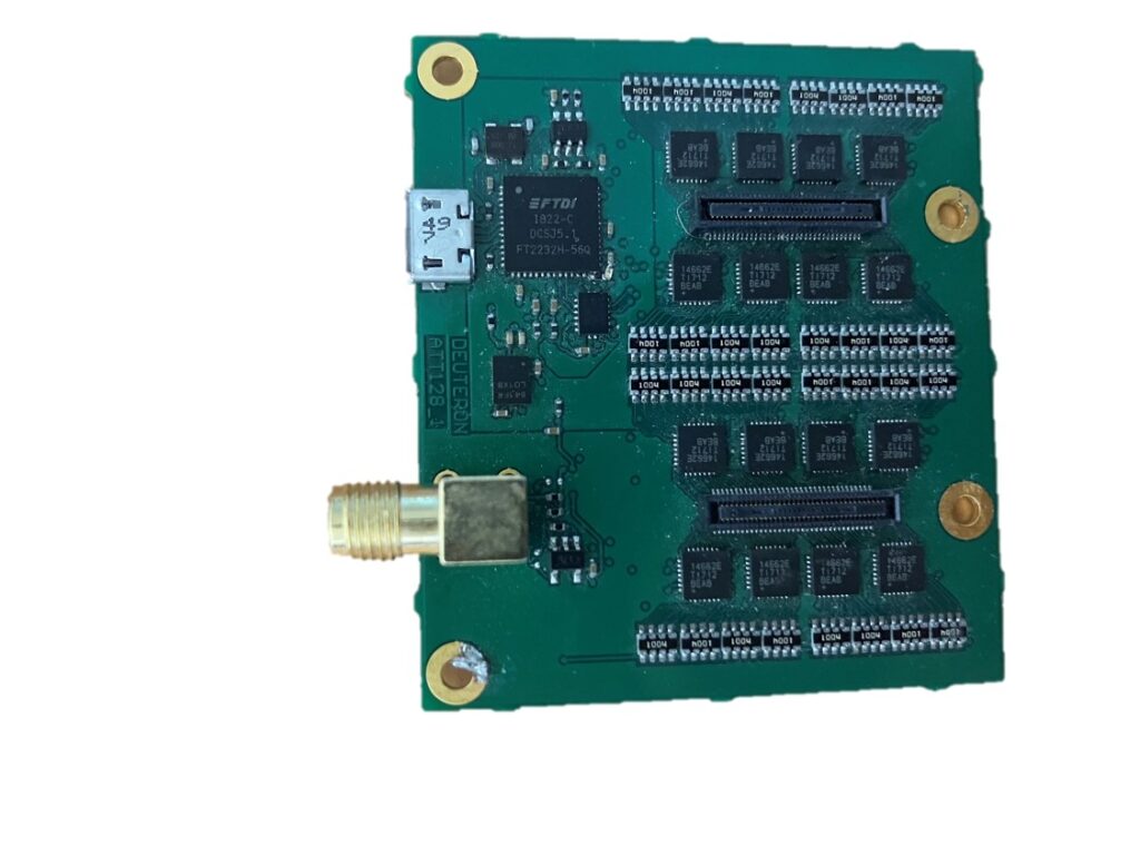
Unlike the Attenuator Test Accessories for lower numbers of channels, the 128-channel version uses electronic switches rather than mechanical ones. These are powered and controlled using a USB connector with the software provided.